Arduino Digital vs Analog Pins Explained (Beginner’s Guide + Example Code)
Introduction
On your Arduino Uno, you’ll see two sets of mysterious labels: Digital Pins (0–13) and Analog Pins (A0–A5). But what’s the difference? When do you use analog vs digital? And what on earth is PWM (~)?
This guide breaks it down clearly—with example wiring + Arduino code you can copy and paste.
By the end, you’ll know exactly:
- How digital pins work (ON/OFF)
- How analog pins work (continuous values)
- What PWM pins do (fake analog output)
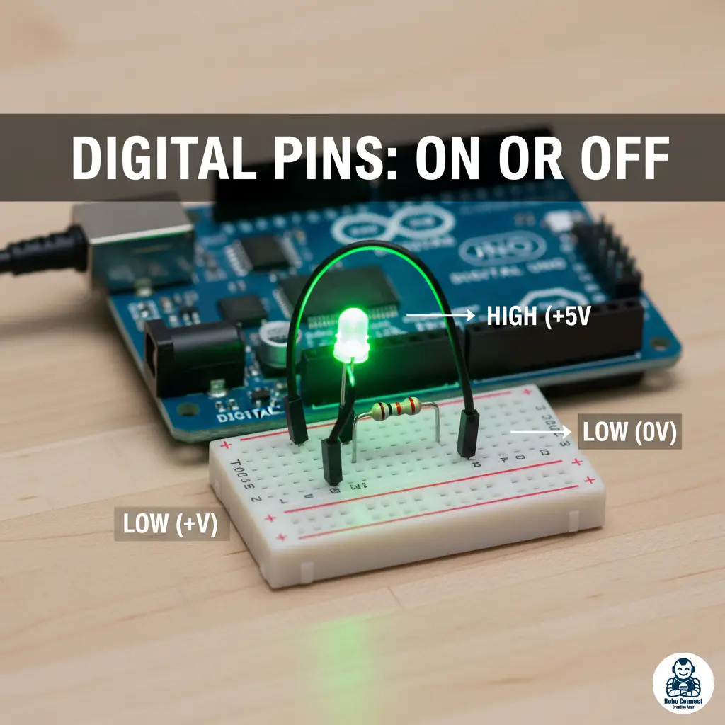
Digital Pins
Can only be HIGH (1, ON, ~5V) or LOW (0, OFF, 0V).
Perfect for LEDs, buttons, and ON/OFF sensors.
🔵 Example 1: Digital Input (Button → LED)
Wiring:
Button between pin 2 and 5V (use pull‑down resistor, or internal pullup).
LED + resistor to pin 13.
Code:
C++
int buttonPin = 2; // Button input
int ledPin = 13; // LED output
int buttonState = 0; // Variable to store button state
void setup() {
pinMode(buttonPin, INPUT); // Set pin 2 as input
pinMode(ledPin, OUTPUT); // Set pin 13 as output
}
void loop() {
buttonState = digitalRead(buttonPin); // Read button
if (buttonState == HIGH) {
digitalWrite(ledPin, HIGH); // Turn LED on
} else {
digitalWrite(ledPin, LOW); // Turn LED off
}
}
💡 Press the button → LED turns on. Release → LED turns off.
PWM Pins (~)
- Some digital pins (~3, ~5, ~6, ~9, ~10, ~11) can do PWM (Pulse Width Modulation).
- PWM simulates analog output (like 0–255 brightness levels).
- Used to dim LEDs or control motor speed.
🟢 Example 3: PWM Output (Fade an LED)
Wiring:
- LED + resistor → pin 9.
Code:
C++
int ledPin = 9; // LED connected to PWM pin ~9
int brightness = 0;
int fadeAmount = 5;
void setup() {
pinMode(ledPin, OUTPUT);
}
void loop() {
analogWrite(ledPin, brightness); // Set brightness (0–255)
brightness = brightness + fadeAmount;
if (brightness <= 0 || brightness >= 255) {
fadeAmount = -fadeAmount; // Reverse direction
}
delay(30); // Delay to see fading
}
💡 The LED smoothly fades in and out—thanks to PWM.
FAQs
Q: Can I use analog pins as digital pins?
Yes! A0–A5 can also behave as regular digital input/output pins.
Q: Why do PWM values go 0–255 instead of 0–1023?
PWM is 8‑bit resolution (0–255 steps), while analog inputs are 10‑bit (0–1023).
Q: Do all Arduino boards use 5V pins?
No—some (like Nano 33 IoT, MKR) use 3.3V logic. Check your specs.
Common Beginner Mistakes
- ❌ Using digitalRead on an analog sensor → you’ll only see HIGH/LOW, not levels.
- ❌ Trying analogWrite() on non‑PWM pin → won’t work.
- ❌ Forgetting the GND connection for sensors → no reference = no readings.
Conclusion
- Digital pins handle ON/OFF (switches, LEDs).
- Analog pins read ranges of values (sensors).
- PWM pins (~) simulate analog outputs (fade LEDs, control speed).
Once you master this difference, you’ll know exactly where to plug in your LEDs, sensors, and motors.