How to Build a Line Follower Robot (Step by Step Guide)
Introduction
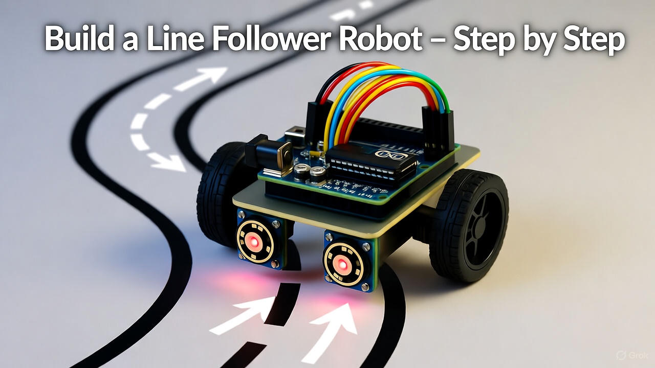
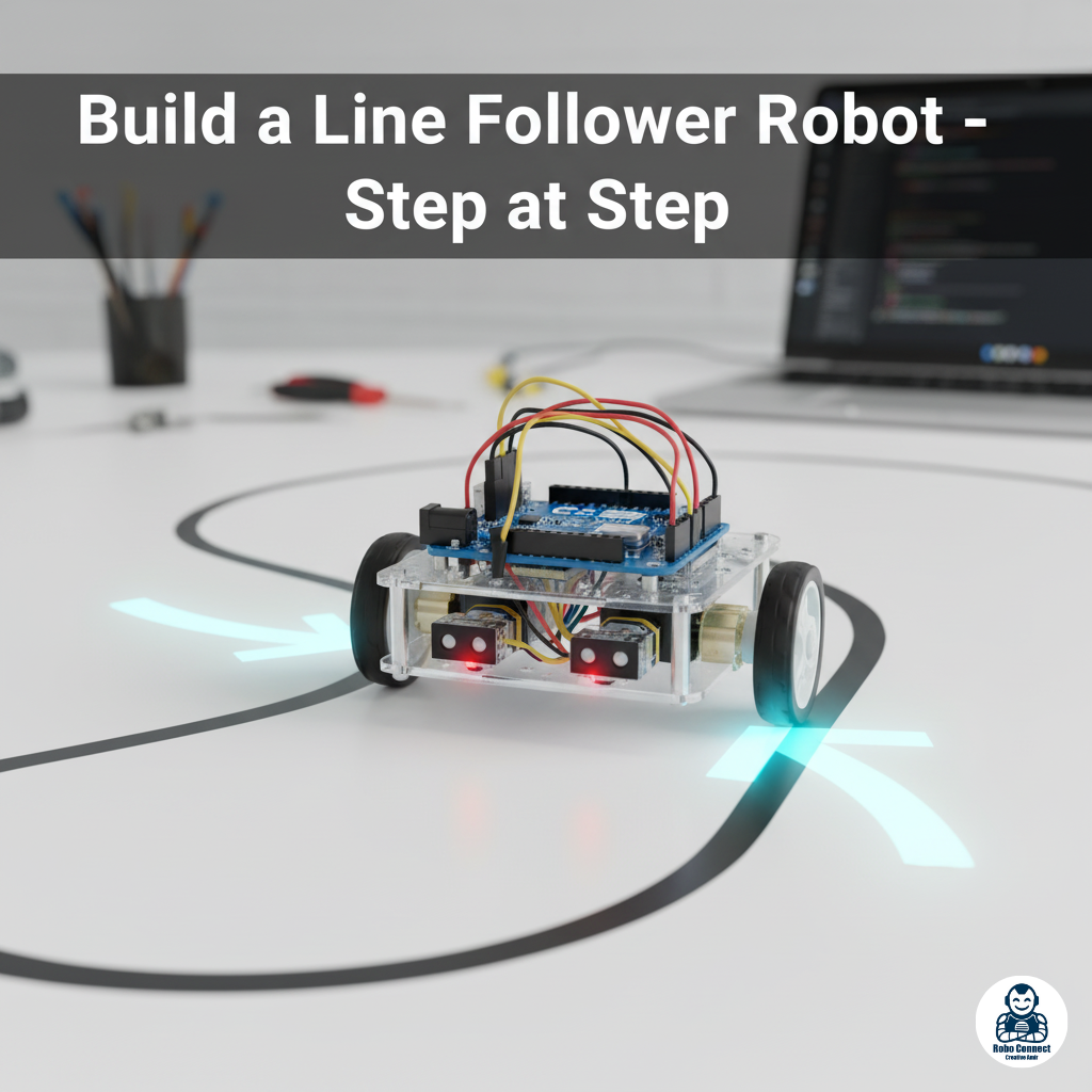
A Line Follower Robot is one of the most popular beginner robotics projects. It’s a robot car that uses infrared (IR) sensors to detect and follow a path (usually a black line on a white surface).
This project teaches the core of robotics:
- Sensing the environment (IR sensors).
- Processing logic (Arduino brain).
- Acting on decisions (DC motors moving left/right).
In this guide, we’ll build a simple Line Follower Robot step by step.
What You’ll Need (Components List)
- Arduino Uno (or Nano)
- L298N Motor Driver Module
- 2x DC Motors + Wheels
- IR Sensor Module (2 or 3 sensors for better accuracy)
- Robot Chassis with battery (6V/9V)
- Jumper wires + breadboard (optional)
- Black tape/marker line on a white surface (track)
Kits are available online as “Arduino Car Kit with Line Sensors” — a good starting point for beginners.
How Does It Work?
- White surface reflects IR light → Sensor = HIGH (logic 1).
- Black line absorbs IR light → Sensor = LOW (logic 0).
The Arduino constantly reads the left & right sensor values:
- If both read white → Move forward.
- If left sensor sees black → Turn left.
- If right sensor sees black → Turn right.
- If both see black → Stop.
This simple logic lets it follow a line track automatically.
Circuit Wiring
Connections overview:
- IR Sensor OUT pins → Arduino digital pins (e.g., D2 = Left, D3 = Right).
- Motor driver IN pins → Arduino pins (D8–D11).
- Motor driver OUT → Two DC motors.
- Motor power supply → 6–12V battery.
- Servo pins:
- Arduino GND → IR & motor driver GND.
- Arduino 5V → IR sensors’ VCC.
(Insert Wiring Diagram: Arduino + L298N + IR Sensors + Motors)
Arduino Code for Line Follower (2‑Sensors Version)
C++
// Pin setup
int leftSensor = 2;
int rightSensor = 3;
int motorA1 = 8;
int motorA2 = 9;
int motorB1 = 10;
int motorB2 = 11;
int leftValue, rightValue;
void setup() {
pinMode(leftSensor, INPUT);
pinMode(rightSensor, INPUT);
pinMode(motorA1, OUTPUT);
pinMode(motorA2, OUTPUT);
pinMode(motorB1, OUTPUT);
pinMode(motorB2, OUTPUT);
}
void forward() {
digitalWrite(motorA1, HIGH); digitalWrite(motorA2, LOW);
digitalWrite(motorB1, HIGH); digitalWrite(motorB2, LOW);
}
void left() {
digitalWrite(motorA1, LOW); digitalWrite(motorA2, HIGH);
digitalWrite(motorB1, HIGH); digitalWrite(motorB2, LOW);
}
void right() {
digitalWrite(motorA1, HIGH); digitalWrite(motorA2, LOW);
digitalWrite(motorB1, LOW); digitalWrite(motorB2, HIGH);
}
void stopRobot() {
digitalWrite(motorA1, LOW); digitalWrite(motorA2, LOW);
digitalWrite(motorB1, LOW); digitalWrite(motorB2, LOW);
}
void loop() {
leftValue = digitalRead(leftSensor);
rightValue = digitalRead(rightSensor);
if (leftValue == HIGH && rightValue == HIGH) {
forward(); // On white → move forward
}
else if (leftValue == LOW && rightValue == HIGH) {
left(); // Left sensor on black → turn left
}
else if (leftValue == HIGH && rightValue == LOW) {
right(); // Right sensor on black → turn right
}
else {
stopRobot(); // Both on black → stop
}
}
Step‑by‑Step Build Process
- Assemble the robot chassis → mount motors + wheels.
- Attach IR sensors facing downward (1–2 cm above surface).
- Connect circuits (Arduino → Motor Driver → Motors → Sensors).
- Upload the given Arduino code.
- Place the robot on the track (black tape on white floor).
- Watch your robot automatically follow the line! 🎉
Troubleshooting Tips
- Robot not following line? → Adjust sensor distance to ~1 cm.
- Motors not responding? → Check motor driver wiring.
- Moves in wrong direction? → Swap motor wires or adjust logic in code.
- Wobbly path following? → Use 3 IR sensors (Left, Middle, Right) for smoother tracking.
Advanced Line Follower Ideas
Once the basic robot works, try:
- Adding speed control via PWM.
- Using 3+ sensors for smoother turning.
- Making a maze solver robot with algorithms.
- Adding Bluetooth/Wi‑Fi for manual override control.
FAQs
Q1: Can I use Raspberry Pi instead of Arduino?
Yes! With Python + GPIO, Pi can do more (like camera‑based line following). Arduino is just simpler for beginners.
Q2: Why does the robot need a motor driver?
Because Arduino pins can’t supply the high current motors need.
Q3: How can I make the track?
Use black electrical tape on white cardboard or floor.
Conclusion
Building a Line Follower Robot is one of the best ways to understand the pillars of robotics:
- Sensors reading input.
- Arduino brain making decisions.
- Motors acting as output.
It looks fun, works practically, and sets the foundation for more advanced AI/robotics projects.
Start with the basic 2‑sensor version today — then upgrade with more sensors and smarter code tomorrow.